2025 Badge Programmer
Design a custom animation below, then beam it to your badge with light. Put the badge in Mode 3 (IR Programming), hold the photodiode to the flashing area, and follow the on-screen steps. Full instructions are in Mode 3 below.
Tip: turn your screen brightness all the way up for the most reliable transfer.
Assembly
Parts List
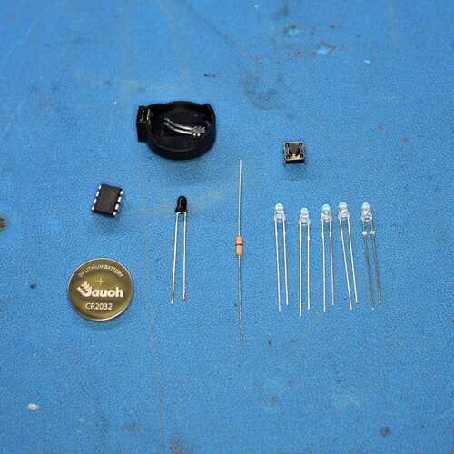
Make sure you have the following parts in your kit:
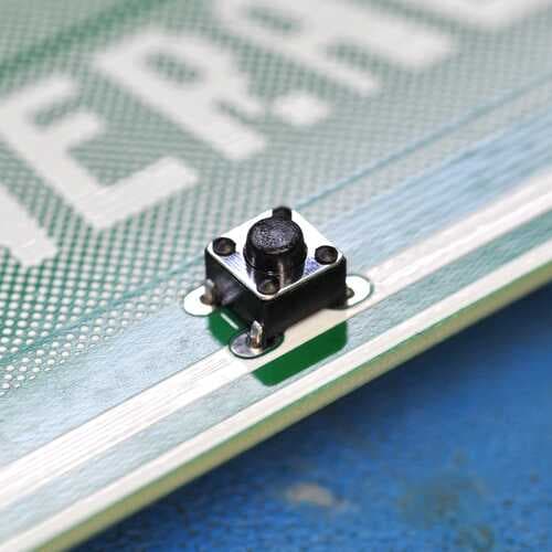
- One 5mm Button
- One CR2032 Battery Clip
- One CR2032 Battery
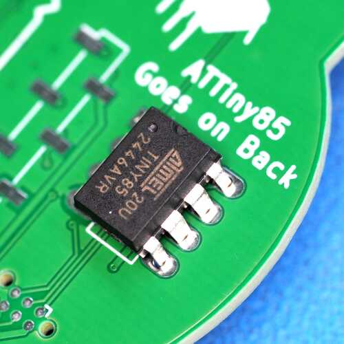
- One ATTiny85 Microcontroller (looks like a black rectangle with 8 pins)
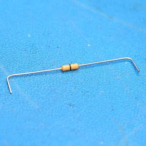
- One 0 Ohm Resistor
- Five LEDs (Clear Lens, Makes Red Light)
- One IR Photodiode (Black Lens)
Read all instructions before assembly!
Do not start soldering until you have read through every step.
- 1
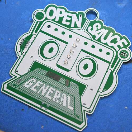
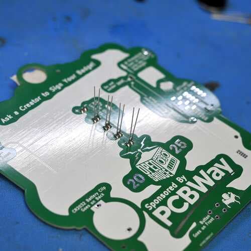
Solder in the five LEDs to the holes in the middle of the badge. The LEDs should be on the front side of the badge — the side with the robot's face. Make sure you put the long leg of the LED through the oval shaped holes.
- 2
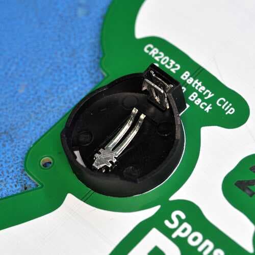
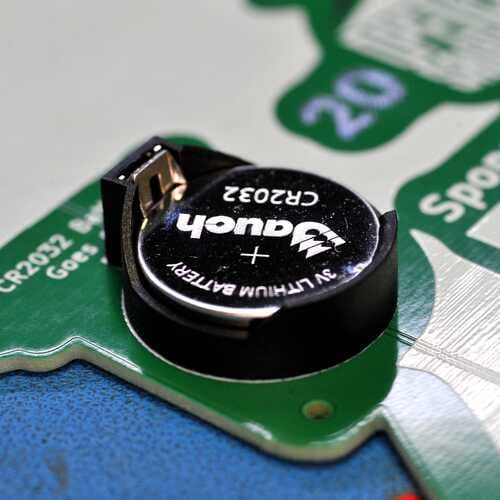
Solder the CR2032 battery clip to the back of the badge. There is a white outline showing you the orientation to solder the clip — make sure you solder it the right way around. The little rectangular nub should be facing up.
- 3
Solder the ATTiny85 to the back of the badge. If you look closely at the chip, you should see a little notch on one end. Make sure that notch is facing up. The ATTiny is pre-programmed — you do not have to program it.
- 4
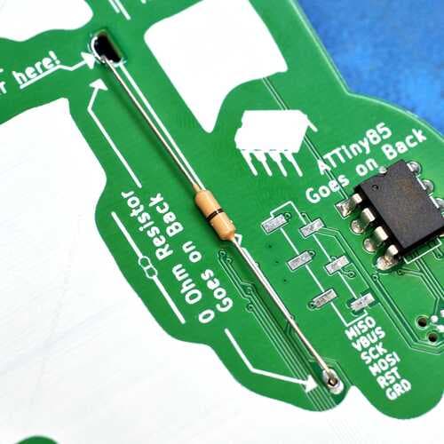
Now solder the 0 Ohm resistor. This part requires some explanation: the resistor acts as a cantilever and is designed to shake back and forth when you shake your badge. While shaking, the top part of the resistor should come in contact with the metal plated side of the top hole. Bend the legs of the resistor as shown, then solder the bottom leg through the hole.
Do not solder the top hole!
- 5
Solder the 5mm button to the front of the badge.
- 6
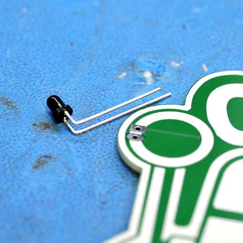
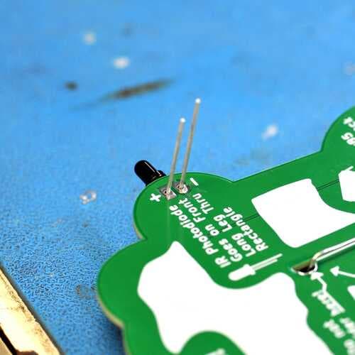
(Optional) Pay close attention here! Bend the IR photodiode at a 90 degree angle so it is facing to the side of your badge, then solder the long leg through the oval hole. Yes, you read that right — the long leg through the oval hole. The back of the badge says to put the long leg through the rectangle hole. That is wrong! We messed up.
Long leg → oval hole (ignore the silkscreen).
- 7
Make sure your parts are all soldered correctly and nothing is bridged.
- 8
Insert a CR2032 battery into the battery clip. The top side of the battery with the + should be facing up.
- 9
Hold down the 5mm button for a couple seconds. The LEDs should all flash, the first LED should flash, and then it should turn off. If it does that, it works!
Usage
Badge Modes
The badge has four different modes:
1
POV Display
2
Resistor Tune
3
IR Programming
4
EEPROM Erase
Switching Badge Modes
Press the 5mm button, wait for an LED to turn on, and then quickly release the button before the LED turns off. If you keep doing this, you will see the LEDs cycle on the badge. LED 1 being lit corresponds to mode 1, LED 2 to mode 2, and so on.
Using a Badge Mode
Cycle the modes until you are one mode before your desired mode, then press and continue to hold the button until the LED turns off. For example, to use mode 1 from mode 2:
- Quick press to get to mode 3
- Quick press to get to mode 4
- Hold to boot the badge and start in mode 1 — keep holding as long as you are using it.
Mode 1: POV Display
POV stands for “Persistence of Vision.” In this mode, when you shake your badge back and forth you should see the letters O P E N S A U C E spelled out one by one. Make sure you have tuned your resistor first, or this will not work. Getting it right takes a little practice, but it’s easy once you get the hang of it.
Mode 2: Resistor Tuning
The 0 ohm resistor needs to be bent at just the right angle for the POV to work — it should almost touch the gold plated side of the top hole. Mode 2 helps you dial this in: when the resistor is making contact with the side of the hole, the first LED lights up. Your resistor is bent properly when the first LED flashes while you shake the badge back and forth in this mode.
Mode 3: IR Programming
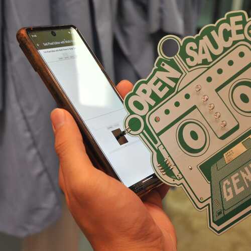
By default your badge displays “O P E N S A U C E,” but you can reprogram it to display whatever you want! Use the programmer above to create your own custom animation. Once you’re done:
- Press the “Start Flashing” button on the website.
- Switch to badge mode #3.
- Hold the photodiode on the left side of your badge up to the center of the flashing part of the website. You must hold the badge there until all steps are complete.
- LED 1 should start flashing in sync with the website.
- Wait for LED 2 to turn on — this shows when the badge is ready to be programmed. This can take from a few seconds to over 20, depending on conditions.
If you’re having trouble:
- Make sure your screen is turned to max brightness.
- Point the photodiode directly at your screen, not at an angle.
- Move away from bright ambient light (like the sun).
- Press the “Transmit Data” button on the website.
- Wait for the programming to complete — time depends on the length of your animation.
- Done! Your badge should now display the new animation.
Mode 4: EEPROM Erase
If you have programmed a custom pattern into the badge with IR programming, this mode lets you erase it and return to the stock “O P E N S A U C E” message. Simply put the badge in this mode and keep holding the button until all the LEDs stop flashing.